Superconducting RF Group
The Polarized SRF
Gun Experiment
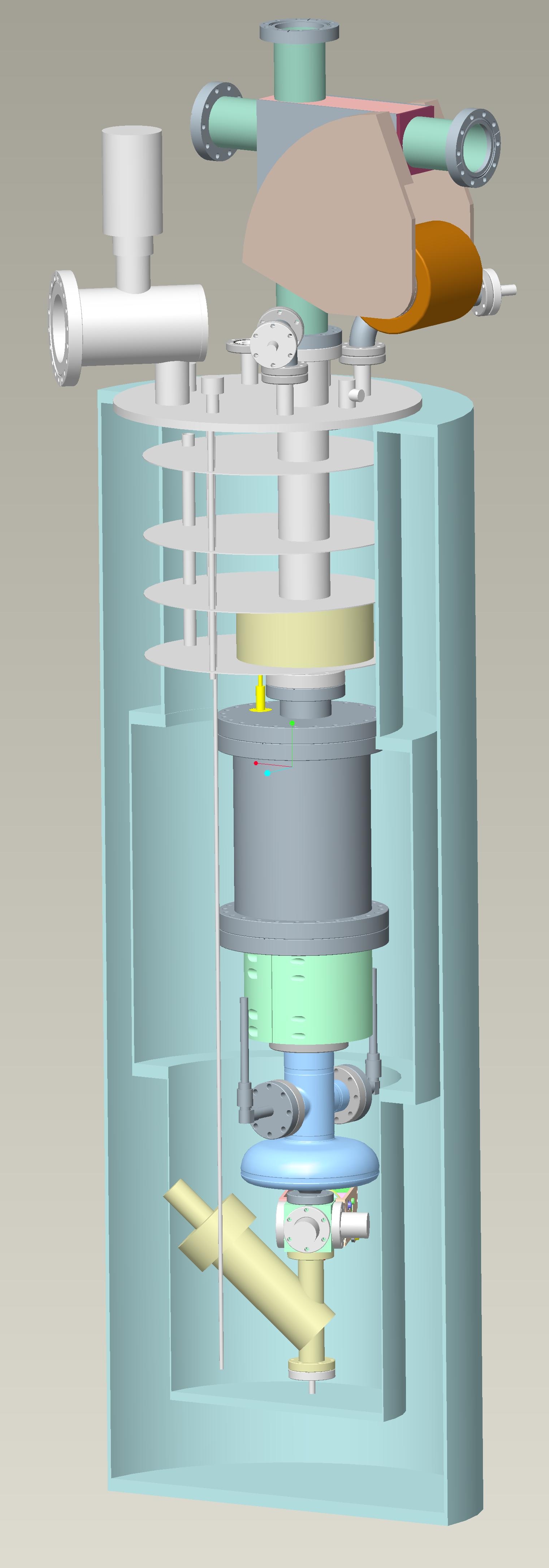 Layout: In the experiment we will operated a ½ cell 1400
MHz SRF gun in a cryostat as shown in the picture on the left. The electron
beam will be accelerated in the gun to an energy of 0.8 MeV and exit the
cryostat on the top.
Layout: In the experiment we will operated a ½ cell 1400
MHz SRF gun in a cryostat as shown in the picture on the left. The electron
beam will be accelerated in the gun to an energy of 0.8 MeV and exit the
cryostat on the top.
The beam pipe has a ceramic break at the exit of the gun, so that the
electron current leaving the gun can be measured. The ceramic is protected
against damage by a G10 sleeve (light green). The picture shows also (in
grey) the canister filled with NEG vacuum pump elements, which are used to
maintain ultra high vacuum when the gun is not cold. A solenoid magnet
(yellow) is used to focus the electron beam. This magnet is placed inside of
the aluminum baffles that are used as a heat shield. This position is above
the liquid helium level, but it is cold enough for high temperature
superconducting coils. Outside the cryostat the beam will be bent by 90o
using a normal conducting dipole. The beam is then sent into a Faraday cup
(not shown in this picture, coming soon). A window in the vacuum pipe above
the dipole allows shining a Laser beam onto the cathode which releases the
electrons from the cathode.
Below the gun is a valve, which is part of a mechanism allowing replacement
of the cathode.
Since we expect degradation of the quantum efficiency of the cathode (this
is what we want to measure), it is important to be able to move the cathode
from the gun to a preparation chamber (shown below). This has to be done
without breaking the vacuum or the cathode will immediately be “gunked up”
by vapors of H2O, CO2, O2 and others. For
that purpose the cathode is mounted on the tip of a “cathode plug”, shown in
red in the below picture.
For the replacement of the cathode the gun assembly is removed from the
cryostat. A transport mechanism is connected to the gun valve. The space
between the two valves is pumped down before the valves are opened. A
magnetic actuator is then used to grab the cathode plug with a bayonet
connector and retract it into the transporter. The valves are closed and the
transporter is disconnected and then attached in the same way to a cathode
preparation chamber. After regeneration of the cathode the procedure is
repeated to move the plug back into the gun. This arrangement is designed
and will be built by AES.
![]()
Figure 1: Transport mechanism and cathode plug
![]()
![]()
Figure 2: Gun assembly with attached transporter
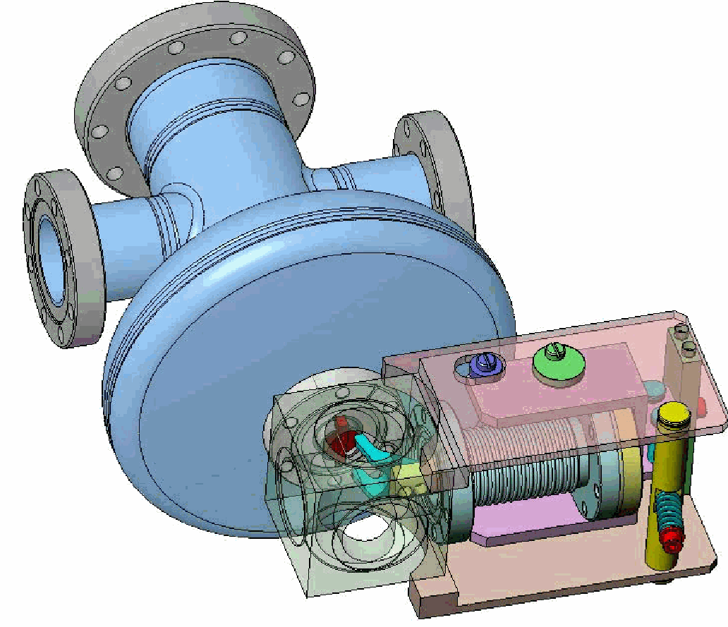
Figure 3: Clamp mechanism to hold cathode in place when detached from the transporter
Figure 4: Preparation chamber with attached transporter
Introduction
Cool down test in Feb 08
Time line
Publications